Welcome to the Chrous 705 Manual, your comprehensive guide to unlocking the full potential of this innovative device. Designed for both new and experienced users, this manual provides detailed insights into setup, operation, and troubleshooting, ensuring optimal performance and productivity.
1.1 Overview of the Chrous 705 Device
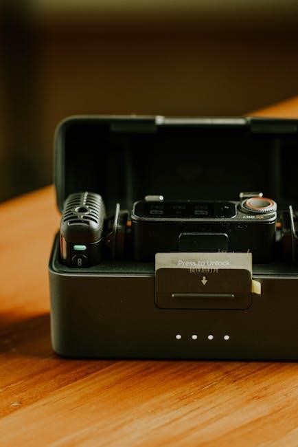
The Chrous 705 is a cutting-edge device designed to deliver exceptional performance and versatility. Its sleek design and user-friendly interface make it accessible to both beginners and professionals. The device is tailored for efficient operation, offering a range of features that cater to diverse applications. With advanced functionality and robust construction, the Chrous 705 is built to meet the demands of modern workflows. This overview provides a foundational understanding of its capabilities, helping users appreciate its value and effectiveness in various scenarios.

System Requirements for Chrous 705
The Chrous 705 requires a minimum of 4GB RAM, 2GHz dual-core processor, and 10GB storage. For optimal performance, 8GB RAM and a quad-core processor are recommended.
2.1 Minimum and Recommended Specifications
To ensure smooth operation, the Chrous 705 requires specific hardware specifications. The minimum requirements include a 2GHz dual-core processor, 4GB RAM, and 10GB of free storage space. For enhanced performance, a 2.5GHz quad-core processor, 8GB RAM, and 20GB storage are recommended. Additionally, a 64-bit operating system is necessary. Meeting these specifications ensures optimal functionality and efficiency. Users should verify their system meets these requirements before installation to avoid performance issues. Proper alignment with these specs guarantees a seamless experience with the Chrous 705 device.

Installation and Setup Guide
Install the Chrous 705 by downloading the latest software from the official website. Ensure your system meets the minimum specifications for a smooth setup process. Follow the on-screen instructions carefully to complete the installation and initial configuration. This guide will walk you through preparing your device for optimal performance and functionality.
3.1 Step-by-Step Installation Process
Begin by downloading the Chrous 705 software from the official website. Ensure your system meets the specified requirements. Launch the installer and follow the prompts to select the installation location. Agree to the terms and conditions, then proceed with the installation. Once complete, restart your system to apply changes. Open the Chrous 705 application, enter your license key, and complete the initial setup wizard. Configure any additional settings as needed to tailor the software to your preferences. Your device is now ready for operation.
Navigating the Chrous 705 Interface
The Chrous 705 interface is designed for intuitive navigation, featuring a clean layout with accessible menus, toolbars, and panels. Familiarize yourself with the main sections to enhance productivity and streamline workflows.
4.1 Key Features and Controls
The Chrous 705 interface features a main dashboard with quick-access buttons for common functions. A sidebar navigation panel allows easy switching between modules. The control toolbar at the top provides shortcuts for frequently used actions. The central workspace is customizable, enabling users to organize tools and displays according to their workflow. Additional features include a preset library, real-time data visualization, and an integrated help system. Customizable shortcuts and multi-touch gestures further enhance efficiency, making the interface adaptable to individual preferences and workflows.

Basic Operations and Functions
Learn essential tasks like device startup, interface navigation, and primary function execution. Understand basic controls and settings to perform fundamental operations efficiently and effectively.
5.1 Getting Started with Chrous 705
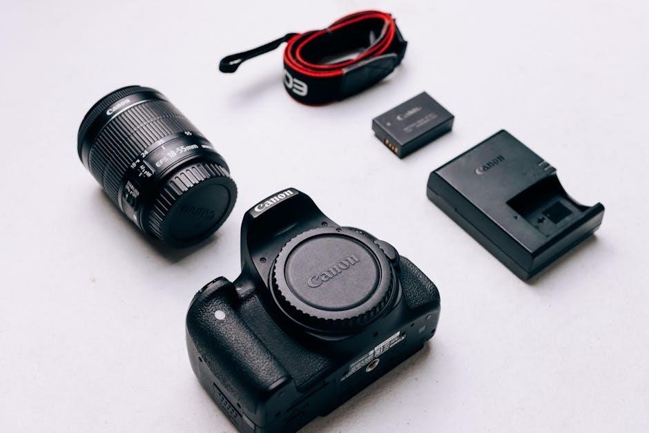
Welcome to the Chrous 705! This section guides you through the initial setup and familiarization process. Start by carefully unpacking the device and connecting any necessary peripherals. Power on the system and follow the on-screen instructions for the first-time setup, which includes language selection and basic configuration. Once initialized, explore the intuitive home screen to access primary functions and customize your experience. Familiarize yourself with the navigation controls and essential features to ensure a smooth and productive workflow from the start.
Advanced Techniques and Customization
Unlock the full potential of the Chrous 705 by exploring advanced features and customization options. Tailor settings, enhance functionality, and streamline workflows for a personalized experience.
6.1 Maximizing the Potential of Chrous 705
To maximize the potential of the Chrous 705, explore advanced customization options such as preset adjustments, automation, and sequencing. Utilize MIDI mapping to streamline workflows and enhance creativity. Experiment with layering sounds and effects to create unique compositions. Optimize performance by allocating resources efficiently, ensuring smooth operation during complex tasks. Discover hidden features through the manual and online resources to unlock new possibilities. Regular updates and community-driven content can further expand your toolkit, keeping your Chrous 705 at the forefront of your creative process.

Troubleshooting Common Issues
Identify and resolve errors by checking connections, updating software, and consulting the manual. Address issues like response delays or overflows promptly to ensure smooth operation.
7.1 Diagnosing and Resolving Errors
Diagnosing errors in the Chrous 705 involves checking connections and system responses. If response times are delayed (100-300 ms), ensure software is updated. Address overflows by reviewing data inputs. For software glitches, restart the device or reinstall updates. Consult the manual for specific error codes and solutions. If issues persist, contact support for further assistance. Regular maintenance can prevent recurring problems, ensuring smooth operation and optimal performance.
Maintenance and Updates
Regularly check for firmware updates and install them to ensure optimal performance. Clean the device to prevent dust buildup and maintain functionality. Follow manufacturer guidelines for reliability.
8.1 Keeping Your Chrous 705 Up-to-Date
Regular updates are essential for maintaining peak performance and security. Check the control panel for firmware updates and install them promptly. Enable auto-update for convenience. Always back up data before updating to prevent loss. Visit the official website for download links and follow instructions carefully. Clean the device periodically to ensure smooth operation. Refer to the manual for detailed maintenance schedules. Stay informed about new features and improvements through notifications or newsletters. Consistent updates ensure compatibility with new software and hardware. Prioritize updates to avoid potential issues and keep your Chrous 705 running efficiently.
Best Practices for Optimal Performance
Follow guidelines for regular maintenance, ensure proper device cleaning, and keep firmware updated to enhance functionality and longevity of your Chrous 705.
9.1 Tips for Efficient Use of Chrous 705
To maximize efficiency with the Chrous 705, prioritize regular firmware updates and organize your workspace to reduce clutter. Use power-saving modes during idle times and consult the manual for shortcuts. Regularly clean the device to maintain performance and avoid overheating. Familiarize yourself with key controls to streamline operations. By following these tips, you can enhance productivity and extend the lifespan of your Chrous 705, ensuring it operates at its best for all your needs.
Thank you for completing the Chrous 705 Manual. For further assistance, visit our official support website or contact our dedicated customer service team for personalized help.
10.1 Additional Support and Documentation
For continued assistance, visit the official Chrous 705 support website, which offers extensive resources, including FAQs, user forums, and downloadable guides. Contact our customer support team for personalized help or access our comprehensive documentation library for in-depth troubleshooting and advanced tips. Stay updated with the latest software releases and instructional videos to maximize your device’s performance. Our dedicated support network ensures you have everything needed to maintain and enhance your Chrous 705 experience effectively.